
1.- APPLICATION
Manifolds are used as for gauges isolation (2 valves) as use in diferential pressure (3 or 5 valves). As used for gauges isolation are specially useful since include the cutoff valve and bleeding in one only block, which avoid joints leaks. As far as they are used in systems of differential pressure, the advantage of including in one only block up to 5 valves, makes them indispensable.
Our manifolds are designed to work up to 420 bar (6000 PSI) and 400ºC (752ºF) with the suitable packing materials.
CAUTION: Manifolds are not useful in applications where the fluid is viscous. The small orifice size which the flow pass through could easily catch thick and solid materials and get to block.
2.- INSTALLATION
- Manifolds must be installed in the direction of flow as indicated by the arrow on the body.
2.1.- THREADED MANIFOLDS INSTALLATION
- Pipe connections should be free of dirt and metal shavings, conveniently deburred.
- Several wraps of PTFE tape is recommended for use of pipe joint sealant.
- To provide a leak proof joint, the pipe should be threaded into the end connection "hand tight", using a wrench to tighten the joint an additional 1/2 to 1-1/2 turns past hand tight. Tightening beyond this point may induce excessive stress that could cause failure.
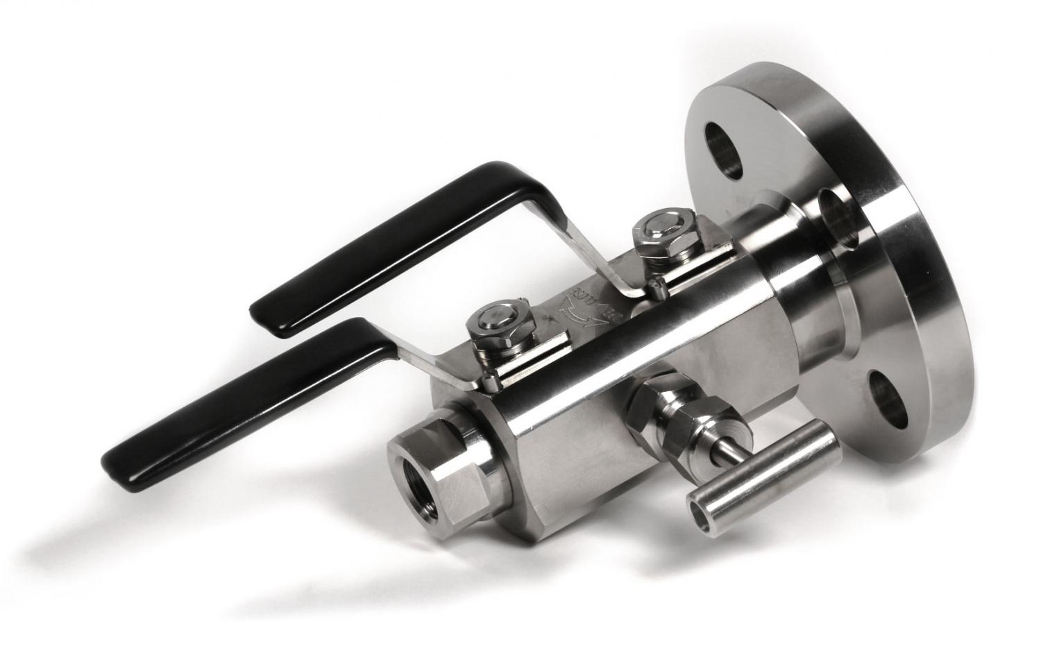
2.2.- MANIFOLDS WITH FLANGE EN 61518 INSTALLATION
- The manifold is supplied with 4 screws and 2 joints to assemble to the transmitter. The distance between center of 2 ports is 54 mm.(2 1/8").
- To make sure an optimal union is advisable to put correctly in the machined slots of the flat side of the flange the 2 joints and tighten the 4 screws alternately in cross to reach an uniform press and avoid leaks.
- FLANGED MANIFOLD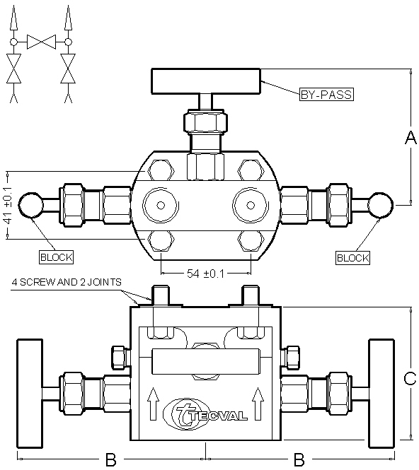 - On the other side, ensure connecting pipes are correctly positioned and supported to avoid any strain on the valves due to the manifolds weight, which ranges between 2,3 - 3 Kgs.
- Manifolds are supplied as per different distribution diagrams, it means that previously the bleed commanding lines must be foressen.
3. OPERATION
- Before activating any element, it’s recommended to have a look to the distribution diagram marked on the body.
- Flow adjustment is achieved by rotation of the handwheel, clockwise to decrease flow and counterclocwise to increase flow.
- To close the manifold use hand force only. Never use spanners or bar extensions.
- When manifolds are used at elevated temperatures, precautions must be taken during operation to prevent burns in hands and damages.
- 2-valve manifolds have a shutoff valve, also called ’block’ and a second valve called ’bleed’ or ’calibration’.
- 3-valve manifolds have 2 block valves, one in each side, and a third valve in the center called ’by-pass’. This third valve in the body center allows levelling the pressure of the two lines. This type of manifold allows to mount small bleed valves in the outlet or in the inlet of the two main lines.
- 5-valve manifolds have two block valves, one in each side, and 3 valves in the body, wich one or two can be ’by-pass’, and the rest could be ’bleed’ valves, as per distribution diagrams (1, 2 or 3). See our Technical Data Sheets.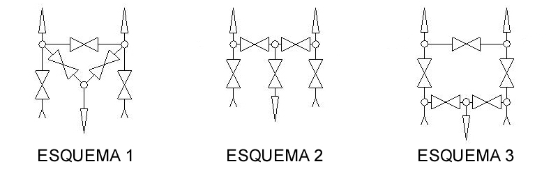 - It’s not recommended to leave the manifold long time without operating. When possible, it should be open/closed at regular intervals to ensure proper and continuous operation.
4.- MAINTENANCE
- Wait until system is depressurized and cold.
- When using dangerous fluids, before carrying out any maintenance operations, drain the system and perform a test in the workbench before installing again.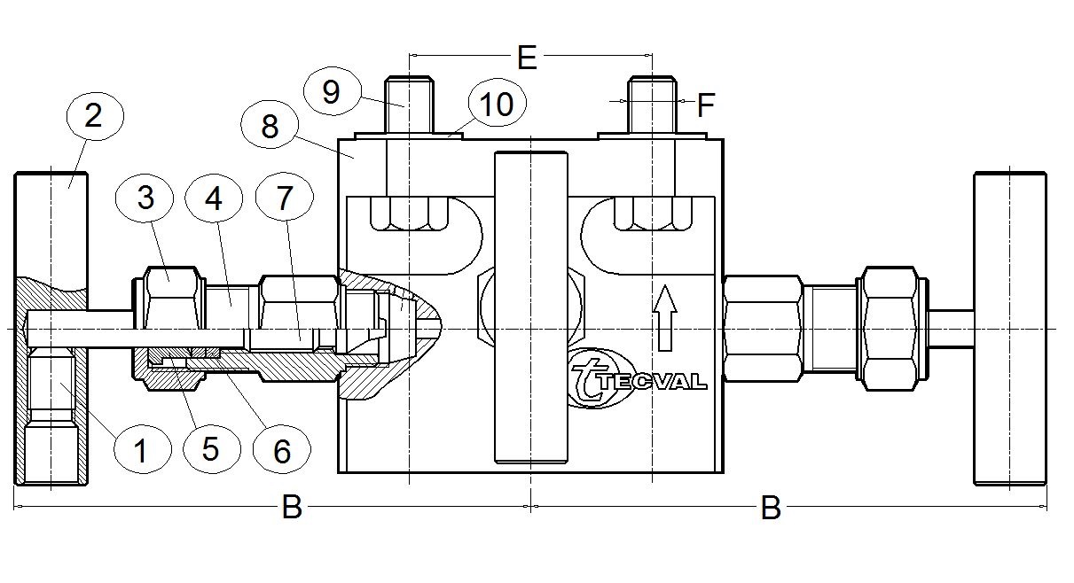 - To adjust the packing, open the valve one full turn (one turn anticlockwise), tighten the nut (part 3) sufficiently to prevent leakage with the handle (part 2) being acceptably tight to turn.
- When Grafoil packing is used, wait two minutes after tightening the nut (part 3) before checking valve operation.
- Re-pressurize and check both leakage and operation.
- All the valves incorporated in our manifolds own back-seat that allows a free packing change while the valves are in service and depressurized.
- Depending on the criticality of service, provide spare parts and gasket kits.
CAUTION: Bonnet (part 4) must not be removed from body (part 8). Do not disassemble valve while under pressure.