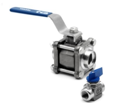

1.- USE
Ball valves are mainly used for shut-off applications, using a handle that is turned 90 degrees or a quarter turn. The rotation of the handle causes the rotational movement of the inner sphere, which performs the function of shutter. Because of the nature of our ball valves, an intermediate position is not advised as this directly results in a premature wear of ball and seats. Our ball valves can be operated up to 210 bar (3000 PSI) and up to 200ºC (392ºF) with the appropriate seat materials. See our Technical Data Sheets.
CAUTION: Ball valves must be lifted in such a way that the body holds the whole weight. Do not lift the valve by the handle or actuator.
2.- INSTALLATION
2.1.- THREADED BALL VALVE INSTALLATION
- Install valve in the open position.
- Pipe connections should be free of dirt and metal shavings.
- Several wraps of PTFE tape are recommended to use as pipe joint sealant.
2.2.- WELDING BALL VALVE INSTALLATION
- Install valve in the open position.
- A proper preparation of the tubing prior to installation is critical to achieve a proper joint. The tubing must be cut square, de-burred, and cleaned with a solvent.
- Do not exceed the 70 ampere of current intensity for welding.
- Wrap the valve body with a damp cloth. (Only for VB-12F)
- Apply heat directing the flame away from the body or center of the valve. Excessive heat can damage the end-connection to body seals and the PTFE seats (Only for VB-12F)
- Ensure ends match and clean carefully the contact surface. Weld the valve to the pipe with 4 joints in every end and remove the internal parts to avoid damages from hot temperature. Complete the welding and wait until it cools down before placing the internal parts again (VB-20 & VB-70)
2.3.- WELDING BALL VALVE INSTALLATION
- Install valve in the open position.
- Make sure the flange’s norm matches. Pipe and valve must be perfectly aligned and have a good support to avoid tension in the junction.
- Use joints between flanges appropiate to the service and center it conveniently.
- Gradually tighten the screws, crossed, moderate and constant.
- Do not force the union of the flanges with the screws when space exists among them.
2.4.- BALL VALVE WITH ACTUATOR
- When adapting pneumatic or electrical actuators, please follow the specific actuator’s manual.
- Make sure you are using the appropriate actuator according to the valve.
- Moderately tighten the joint’s screws if necessary.
3.- OPERATION
- The valve must work only in the positions "fully open" or "fully closed". Leaving the valve in an intermediate position (half-open), may cause severe damage in the seats and seals.
- In valves operated with a handle, when the handle is aligned with the valve’s stem (pipe), it means "open". If the handle is perpendicular (90-degree) to the pipe, it means "closed".
- When valves are used at elevated temperatures, precautions must be taken during operation to prevent burns to hands.
- In valves operated with actuators, these have mechanical indicators showing if the valve is "open" or "closed".
- It is not recommended to leave the valve without operating for a long time. If possible, it should be opened at regular intervals to ensure proper and continuous operation.
4.- MAINTENANCE
- Wait until the system is depressurized and cold.
- When using dangerous fluids and before carrying out any maintenance operations, drain the system and test in the workbench before installing again.
- Perform atmospheric leakage tightness, and if necessary tighten the screws again.
- Inspect the good condition of seats and ball. Clean inner parts. If necessary, replace parts or the full valve.
- Depending on the criticality of service, spare parts and gasket kits are advised.
CAUTION: Do not disassemble the valve while under pressure.
